
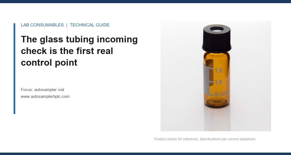
A 2 mL HPLC vial lot shipped last quarter, 50,000 pieces, with a septum that measured 55 Shore A on the Shore durometer when the print said 50. The line supervisor caught it at station 4, not at final QC. That is the difference between a factory that controls the process and one that inspects the result. If you buy autosampler vials, you are buying a set of in-line decisions made by people and sensors at specific stations. This article maps how an autosampler vial is manufactured and what the factory controls, station by station, including which parameters get closed-loop feedback and which only get checked after the batch is already formed.
Most autosampler vial factories do not melt their own glass. They buy borosilicate 3.3 tubing from a handful of converters, then convert it on site. The first station is not a forming machine. It is an incoming inspection bench with a laser micrometer, a polariscope, and a dimensional log that nobody outside the factory ever sees.
What gets checked at this station:
- Outer diameter tolerance. For a 12 x 32 mm vial, the tubing OD is typically 11.6 to 11.8 mm before forming. A drift of 0.05 mm here translates into a neck ID problem three stations later because the forming mandrel cannot compensate for that much glass volume variation.
- Wall thickness variation. Measured at 4 points around the circumference. If the variation exceeds 0.08 mm, the vial will have a visible side-to-side thickness difference after the shoulder is formed. That difference changes the internal volume by more than 1% and shifts the fill line.
- Stress birefringence. The polariscope shows residual stress in the tubing. Tubing with high stress cracks during the shoulder forming step, usually at a rate of 3 to 7 pieces per 1,000. A good incoming lot runs under 1 per 1,000.
- Alkali content. Not measured on every lot. A factory that does USP <661.1> testing will pull a sample and run a flame photometer check. This is a batch-level check, not a line-level one.
This station is manual. The operator records values on a paper form or a tablet. There is no closed-loop control here because nothing on the line can fix bad incoming glass. The decision is binary: accept the lot or reject it. I have seen a factory accept tubing with 0.12 mm wall variation because the purchasing manager did not want to pay return freight. That lot produced 11% scrap at the forming station and the cost came out of the next quarter’s margin.
Tube cutting and the length parameter nobody specs
After incoming inspection, the tubing moves to a cutting station. The machine is a rotary diamond saw or a thermal shock cutter. The control here is length, and the tolerance is tighter than most buyers assume.
For a 32 mm finished vial, the cut blank is typically 31.2 to 31.6 mm, because the shoulder forming step shortens the blank by 0.4 to 0.8 mm depending on the glass temperature. The cutting machine has a servo-driven stop. The operator sets the stop position, and the machine cuts blanks in sequence. A good line checks blank length every 20 minutes with a dial caliper and adjusts the stop if the mean drifts more than 0.1 mm.
This is a semi-closed loop. The machine does not measure its own output. The operator measures, then adjusts. On newer lines, a laser micrometer sits after the cutter and feeds length data to a PLC. If the mean drifts, the PLC nudges the stop position by 0.02 mm increments. That is true closed-loop control, and it is rare. Most factories still run the manual check loop.
The failure mode at this station is not a short vial. It is a vial with a chipped cut edge. A thermal shock cutter that runs too hot produces micro-cracks at the cut end. Those cracks propagate during shoulder forming and create a leak path at the neck. The factory control is a visual check under a 10x loupe, every 200 pieces, looking for radial cracks longer than 0.5 mm.
Shoulder forming: where the mandrel temperature decides the yield
The shoulder forming station is where the cylindrical blank becomes a vial. The blank is loaded into a rotating chuck, heated by a gas-oxygen flame or an induction coil, and a mandrel presses the softened glass into the neck and shoulder profile. This is the highest-scrap station on any autosampler vial line, and the parameters here are the ones a factory guards most closely.
The mandrel temperature is the critical variable. If the mandrel is too cold, the glass sticks and tears. If it is too hot, the glass wets the mandrel and the neck ID comes out oversize. The control band for a 9 mm screw neck is typically 480 to 520 °C at the mandrel tip. A factory that runs closed-loop control uses an infrared pyrometer aimed at the mandrel surface, with a PLC that adjusts the induction coil power every second. A factory that runs open-loop uses a thermocouple in the mandrel body and an operator who checks the readout every 30 minutes. The difference in neck ID standard deviation is about 0.04 mm versus 0.09 mm. That difference decides whether a 9 mm cap seals reliably at 1,000 autosampler injection cycles.
Other controlled parameters at this station:
- Chuck rotation speed. For a 12 mm vial, the blank spins at 600 to 900 rpm during heating. Too slow and the glass sags unevenly. Too fast and the blank wobbles, producing an eccentric neck.
- Flame gas ratio. Oxygen to natural gas or propane is set to produce a neutral flame. A reducing flame deposits carbon on the glass surface, which shows up as a gray haze inside the vial. That haze adsorbs analytes and causes carryover.
- Mandrel dwell time. The mandrel presses into the blank for 0.8 to 2.2 seconds depending on the glass viscosity. A 0.2 second error changes the shoulder angle by 2 to 4 degrees, which shifts the internal geometry enough to change autosampler needle penetration depth.
This station has the most closed-loop control on a modern line, but only for temperature and rotation speed. Mandrel dwell time is usually set by a mechanical cam and checked once per shift. Shoulder angle is not measured in-line on most lines. It is a final QC check with a shadowgraph or a vision system.
Annealing lehr: the parameter that is controlled but not verified in-line
After forming, the vials are still hot and full of thermal stress. They enter an annealing lehr, which is a long tunnel with controlled heating and cooling zones. The goal is to reduce residual stress below a level that would cause spontaneous cracking or failure under thermal cycling.
The lehr has three zones:
- Heating zone. Brings the vial back up to the annealing point of borosilicate 3.3, which is 560 °C. The vial spends 8 to 15 minutes in this zone depending on wall thickness.
- Soak zone. Holds the vial at 560 °C for 10 to 20 minutes to allow stress relaxation.
- Cooling zone. Drops the temperature at 2 to 5 °C per minute until the vial reaches 100 °C. Faster cooling reintroduces stress.
The lehr temperature is closed-loop controlled. Thermocouples in each zone feed a PID controller that adjusts the heating elements. What is not controlled in-line is the actual residual stress in each vial. The factory checks stress with a polariscope on a sample of vials after the lehr, typically 5 pieces per 1,000. If the stress reading exceeds the factory’s internal limit, the entire lot is re-annealed or scrapped. But the lehr itself has no feedback from the polariscope. It is a fixed recipe, verified by sampling.
I have seen a lehr cooling zone drift 8 °C below setpoint for a full shift because a fan bearing was failing. The thermocouple read correctly, the PID held the air temperature, but the air velocity dropped. The vials cooled too fast on one side. Stress birefringence came back at 3 times the internal limit, and the lot cracked during autoclaving at the customer site. The factory control that should have caught this was a weekly air velocity check with a hot-wire anemometer. The line did not have one scheduled.
Surface treatment and the difference between silanization and deactivation
After annealing, some vials go through a surface treatment step. This is where the factory controls what the inside of the vial does to your analyte, and it is the station with the most variation between suppliers.
For standard HPLC vials, no surface treatment is applied. The glass surface is as-formed, with silanol groups that can adsorb basic analytes. For sensitive analytes, the factory offers silanized vials. The control here is a liquid-phase silanization process using a reagent like dimethyldichlorosilane or a vapor-phase process using hexamethyldisilazane. The key parameters:
- Reagent concentration. For liquid-phase silanization, a 5% solution in toluene is common. Higher concentration does not improve coverage; it leaves a residue that extracts into the sample.
- Reaction time. 30 to 60 minutes at room temperature for liquid phase. Vapor phase runs 2 to 4 hours at 60 to 80 °C.
- Rinse steps. After silanization, the vials are rinsed with toluene, then methanol, then dried. Incomplete rinsing leaves silane residue that shows up as ghost peaks in LC-MS.
This station is batch-controlled, not line-controlled. The vials are loaded into a reactor vessel, treated, rinsed, and dried as a lot. The factory checks silanization quality with a contact angle measurement on a sample of vials. A well-silanized borosilicate surface shows a water contact angle of 95 to 105 degrees. Untreated borosilicate shows 20 to 30 degrees. If the contact angle is below 90, the lot is re-treated or downgraded to non-silanized.
Some factories call this “deactivation” and use a different chemistry. The term matters because silanization and deactivation are not the same process. Silanization adds a hydrophobic layer. Deactivation can mean acid washing, base washing, or a polymer coating. If your method is sensitive to surface chemistry, ask the factory which reagent they use and which contact angle they hold. A vague answer means the station is not controlled at all.
Septum punching and the puncture count that predicts coring
The septum is made separately, usually from PTFE laminated to silicone. The PTFE layer faces the sample, the silicone layer provides resealing. The factory controls the lamination at a press station, then punches septa to size.
The punch station is where septum quality is decided. The punch die has a clearance between the punch and the die of 0.02 to 0.04 mm for a 9 mm septum. If the clearance opens up to 0.06 mm, the punch tears the PTFE instead of shearing it. A torn PTFE edge delaminates from the silicone after 20 to 30 needle punctures, and the septum starts leaking.
The factory checks punch sharpness by counting the number of septa punched since the last die sharpening. A carbide punch runs 50,000 to 80,000 cycles before resharpening. A steel punch runs 20,000 to 30,000. The line supervisor tracks the counter and rotates dies on schedule. This is a preventive control, not a measured one. The only way to verify punch quality in-line is to pull a septum every 500 pieces and inspect the edge under a microscope. Most factories do this, but the operator is looking for gross tears, not the 0.01 mm feathering that causes slow leaks.
Septum hardness is measured with a Shore A durometer at the incoming silicone inspection and again after lamination. The spec for a standard HPLC septum is 50 ± 5 Shore A. A septum at 55 Shore A, the one I mentioned at the start, is 10% harder than nominal. That changes the needle penetration force from about 0.8 N to 1.2 N. An autosampler needle with a 23 gauge tip can handle that, but a 26 gauge needle will bend or core the septum. The factory that caught the 55 Shore A lot at station 4 did so because the durometer check was in-line, not final QC.
Assembly and the torque value that nobody writes on the drawing
The cap, septum, and vial come together at the assembly station. For screw caps, the factory uses a capping machine with a torque clutch. For crimp caps, it uses a crimping head with a controlled stroke.
The torque value for a 9 mm screw cap is the parameter that decides whether the vial leaks during transport or during the autosampler run. The factory sets the capping torque to 8 to 12 cN·m for a standard polypropylene cap with a 1.0 mm thick silicone/PTFE septum. Below 8 cN·m, the cap can back off during shipping vibration. Above 12 cN·m, the cap distorts the septum and the PTFE layer wrinkles. A wrinkled PTFE layer does not seal against the vial rim, and the vial leaks at the first injection cycle.
The capping machine has a torque clutch that slips at the set value. The factory verifies the clutch setting at the start of each shift with a torque meter. But the clutch drifts as it heats up. A good line re-checks torque every 2 hours and adjusts the clutch. A bad line sets it once in the morning and runs 8 hours. The drift on a worn clutch can be 1.5 cN·m over a shift, which is enough to move the lot from the center of the torque window to the edge.
For crimp caps, the control is the crimp height. The factory sets the crimping head to compress the aluminum cap to a final height of 8.2 to 8.4 mm for an 11 mm crimp neck. Too low and the cap cuts into the septum. Too high and the cap is loose. The crimp height is checked with a dial indicator every 30 minutes. This is a manual check, not a closed-loop control. The crimping head wears, and the operator compensates by adjusting the stroke.
Washing and the residue level that changes your baseline
After assembly, the vials go through a washing step. This is not a cosmetic step. It removes the release agents, dust, and finger oils that accumulated during forming and assembly. The factory control here is the wash solution, the rinse water quality, and the drying temperature.
The wash solution is typically a dilute alkaline detergent, followed by deionized water rinses. The factory measures the rinse water conductivity and holds it below 1.0 µS/cm. If the DI system is exhausted, the conductivity rises and the vials come out with ionic residue. That residue shows up as a baseline rise in ion chromatography or as adduct peaks in LC-MS.
The drying step uses a hot air oven at 80 to 100 °C for 30 to 60 minutes. The control is the oven temperature and the air filtration. A HEPA filter on the air intake is standard. If the filter is not changed on schedule, the vials come out with particulate contamination. The factory checks for particulates by rinsing a sample of vials with filtered solvent and running the rinse through a particle counter. The internal limit is typically fewer than 10 particles per mL greater than 10 µm.
This station is batch-controlled. The vials are washed in baskets, not individually. The factory pulls a sample from each basket and runs the particle count. If the count exceeds the limit, the basket is rewashed. The wash solution is changed every 4 to 8 hours depending on throughput. A factory that extends the wash solution life to save cost is trading your baseline stability for their chemical budget.
Final dimensional check: what is actually measured at the end of the line
After washing and drying, the vials pass through a final inspection station. On a modern line, this is a vision system with multiple cameras. On an older line, it is a set of go/no-go gauges and a shadowgraph. The factory controls what gets checked here, and the list is shorter than most buyers assume.
The standard final checks for a 12 x 32 mm screw-top vial:
- Vial height. 32.0 ± 0.25 mm. Measured with a laser or a dial gauge.
- Vial OD. 12.0 ± 0.15 mm. Measured at the body, not the neck.
- Neck ID. 9.0 ± 0.1 mm for a 9 mm screw neck. Measured with a plug gauge or a vision system.
- Neck thread profile. Checked against a master cap by torque testing a sample. The cap must engage fully and hold at the specified torque.
- Shoulder angle. Checked on a shadowgraph. The internal shoulder angle is typically 120 to 130 degrees. A deviation of 5 degrees changes the needle path.
- Visual defects. Cracks, chips, bubbles, and foreign inclusions. Checked by vision system or human inspector.
What is not measured at final inspection on most lines:
- Internal volume. The factory calculates it from the dimensions, but does not measure it directly. A vial with the correct OD and height can still have an internal volume that is 3% off if the wall thickness varies.
- Residual stress. Checked on a sample, not every vial.
- Surface energy. Checked on a sample for silanized vials only.
- Septum resealability. Not tested at final inspection. The factory relies on the septum material spec and the punch station controls.
The final dimensional check is a filter, not a control. It catches gross defects. It does not catch the slow drift in mandrel temperature that shifted the neck ID by 0.05 mm over a shift. That drift was either controlled at the forming station or it was not. By the time the vial reaches final inspection, the neck ID is whatever the mandrel made it.
Comparison table: closed-loop vs. end-of-line controls on a typical autosampler vial line
| Parameter | Station | Control type | Typical spec | Verification frequency |
|---|---|---|---|---|
| Mandrel temperature | Shoulder forming | Closed-loop (IR pyrometer + PLC) | 480 to 520 °C | Continuous |
| Chuck rotation speed | Shoulder forming | Closed-loop (encoder + servo) | 600 to 900 rpm | Continuous |
| Blank length | Tube cutting | Semi-closed (operator adjusts) | 31.2 to 31.6 mm | Every 20 min |
| Lehr zone temperature | Annealing | Closed-loop (thermocouple + PID) | 560 °C soak, 2-5 °C/min cool | Continuous |
| Residual stress | Post-annealing | End-of-line (polariscope) | Below internal limit | 5 per 1,000 pieces |
| Capping torque | Assembly | Semi-closed (torque clutch + check) | 8 to 12 cN·m | Every 2 hours |
| Crimp height | Assembly | Manual (dial indicator) | 8.2 to 8.4 mm | Every 30 min |
| Septum Shore A hardness | Incoming + post-lamination | Manual (durometer) | 50 ± 5 Shore A | Every lot + every 500 pieces |
| Rinse water conductivity | Washing | Manual (conductivity meter) | Below 1.0 µS/cm | Every basket |
| Neck ID | Final inspection | End-of-line (plug gauge or vision) | 9.0 ± 0.1 mm | 100% or sample |
| Internal volume | Not measured | Calculated from dimensions | Typically ± 3% | Never directly |
Field case 1: the neck ID drift that final QC missed
A contract lab running a 96-vial overnight sequence on an Agilent 1290 autosampler started seeing intermittent needle crashes. The needle would descend, hit the vial rim instead of the opening, and the run would abort. The lab pulled the vial lot and measured the neck ID with a calibrated plug gauge. The mean was 9.04 mm, within spec. But the standard deviation was 0.11 mm, and the distribution was bimodal. About 12% of the vials had a neck ID below 8.85 mm. Those vials were the ones the needle hit.
The root cause was at the shoulder forming station. The mandrel temperature had been drifting down over a 4-hour period because the IR pyrometer lens was fogged with glass volatiles. The PLC was reading a temperature 30 °C higher than the actual mandrel surface. The operator did not notice because the readout looked stable. The mandrel was running cold, the glass was not flowing fully around it, and the neck ID came out undersize on every third or fourth cycle.
The fix was a pyrometer lens cleaning schedule every 2 hours and a cross-check with a contact thermocouple once per shift. The factory also added a neck ID check at the forming station, not just at final inspection. That single change moved the neck ID standard deviation from 0.11 mm to 0.04 mm. The lab stopped seeing needle crashes.
Field case 2: the septum lot that passed durometer but failed coring
A pharmaceutical QC lab running a USP monograph method saw a sudden increase in septum coring. The autosampler needle was punching small PTFE discs out of the septum, and those discs were ending up in the sample vial. The lab found the discs during a visual inspection of the injection port. The septum lot had passed the factory’s Shore A durometer check at 51, right in the middle of the 50 ± 5 spec. But the coring rate was 4 times the historical average.
The lab sent the septum lot back to the factory for analysis. The factory’s incoming silicone inspection had not checked the silicone layer thickness. The spec was 1.0 mm, but the actual thickness was 0.82 mm. The thinner silicone layer compressed less under the cap, which changed the effective hardness at the needle penetration point. The PTFE layer was also 0.25 mm instead of the specified 0.30 mm. The thinner PTFE tore more easily under the needle bevel.
The fix was a dual-layer thickness check at the incoming inspection station, using a digital micrometer with a 0.01 mm resolution, measuring both the PTFE layer and the silicone layer separately. The factory also added a coring test to the final QC protocol: a 23 gauge needle mounted in a test fixture, 50 punctures at 1 puncture per second, then visual inspection of the septum under a microscope. The acceptance limit is zero visible PTFE fragments larger than 0.2 mm. The factory that added this test reduced its septum-related customer complaints by 70% in one quarter.
Troubleshooting checklist: what to ask the factory when a vial lot fails
When a lot fails in your lab, the factory will ask for the lot number, the failure mode, and a return sample. Before you send anything, ask these questions. The answers tell you whether the factory controls the line or just inspects the output.
- What was the mandrel temperature during the shift that produced this lot? If they cannot tell you, they are not logging it. If they give you a single number, ask for the trend. A factory with closed-loop control can export the temperature trace.
- What was the capping torque at the start and end of the shift? If the two numbers differ by more than 1 cN·m, the clutch drifted. Ask when the last clutch calibration was done.
- What was the rinse water conductivity for the baskets in this lot? If they do not log conductivity per basket, they are not controlling ionic residue.
- What was the septum Shore A hardness at the incoming inspection and after lamination? If they only measured one of those, the other is uncontrolled.
- How many pieces were pulled for residual stress testing, and what were the readings? If the answer is “we don’t test stress on this product,” you now know the annealing lehr is running blind.
- What is the punch die cycle count for the septum lot? If the die was at 78,000 cycles and the resharpening spec is 80,000, the septa were punched with a dull die.
These questions work because they map to specific stations. A factory that controls the line can answer all of them in 10 minutes. A factory that only inspects the output will start hedging. That hesitation is the signal.
For more on the dimensional tolerances that decide fit, see the Autosampler Vial reference. If you are specifying a Vial for headspace work, the forming and annealing controls differ from HPLC because the internal pressure rating changes. A Headspace Vial factory controls the bottom thickness and the crimp neck geometry more tightly than a standard HPLC vial line. If your method runs on a GC system, the Gc Vial line adds a deactivation step that HPLC vials do not need. For instrument-specific compatibility, check the Agilent chromatography consumables and columns documentation or the Thermo Fisher chromatography and sample handling application notes. If you are running environmental methods, the U.S. EPA SW-846 test methods for waste and materials specify vial cleaning and blank requirements that force tighter washing controls. Restek technical resources for chromatography publishes vial cleanliness data that shows what a controlled washing station should achieve.
The decision rule for buying from a controlled line
Buy from a factory that can show you the mandrel temperature trace, the capping torque log, and the rinse water conductivity record for the lot you are buying. If they cannot produce those three records, you are buying from a factory that inspects the result instead of controlling the process. That factory will ship good vials most of the time, but the failure mode will be intermittent and expensive to diagnose. The three records cost nothing to generate on a modern line. A factory that does not have them is telling you, without saying it, that the line runs open-loop where it matters most.
References & further reading
Related resources from our lab consumables network:
- Autosampler Vial at autosamplerhplc.com
- Vial at vials-filters.com
- Headspace Vial at headspacevialsupplier.com
- Gc Vial at gcvialfactory.com
External references and standards: